How to build a cnc - 15 Project release and indications for modifications
Several people have contacted me to request the project of my 110 cm by 70 cm self-built cnc and, as promised, here it is, available for download in the appropriate section. I remember that you need to register on the site in order to download it. I had the intention, by virtue of the experience gained, to make improvements to the project but, due to various commitments, I did not succeed. The downloadable project, therefore, is the original one. I will shortly provide all the indications I would have liked to apply to improve it so that, if you want, you can modify it yourself. I would be happy, indeed I would like to see what you have done. Below is only a brief summary of the contents of the video regarding the changes to be made and further indications for the realization.
The project, as you can see from the videos on the channel, is designed to be downloaded, printed in 1: 1 format, applied to the various parts and cut out. My cnc was built this way. Obviously, if someone has a CNC, they could also cut out the various parts directly.
The project


ATTENTION: In order to proceed with the construction of the cnc it is necessary to make changes based on the length of the screws that have been purchased. In the video that I will make I will explain how to do it. Therefore, unless you are able to modify the project according to your needs, I advise you to wait for the indications that I will provide in the video.
Summary list of improvements to be made:
PS: The following procedures can also be used just to adapt the design to different screw and rail sizes
1. Changing the length of the X axis (TAV A)
- This modification is useful for not having to create supports for mounting the engine and also allows you to attach and remove the same more easily.


To implement this change:
1 - Fix components BK and BF on the screw
2 - Insert the coupling on the screw
3 - Fix the motor on the coupling joint (making sure that between the end of the screw and the beginning of the motor pin there are at least 3/4 mm)
4 - Measure X
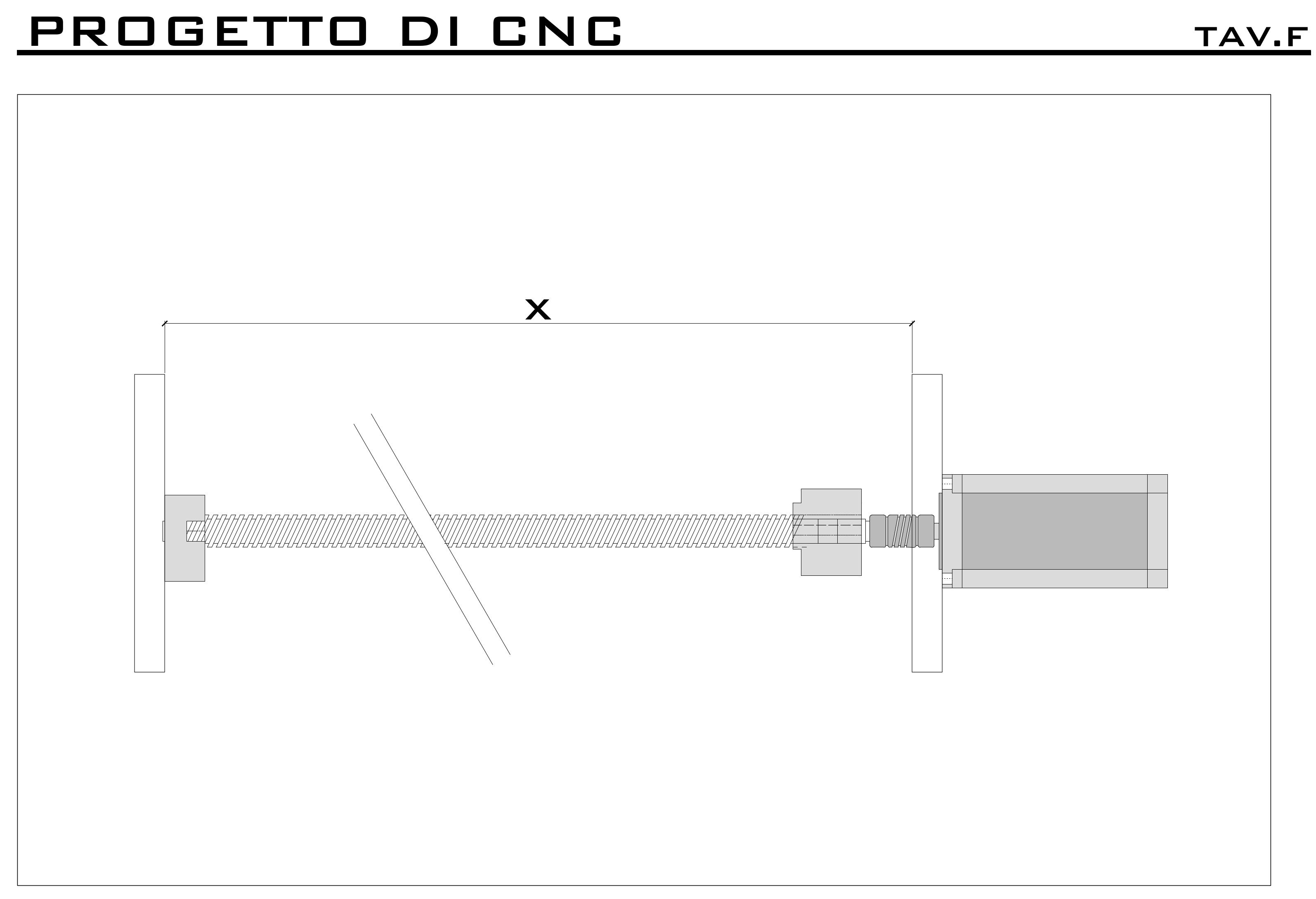
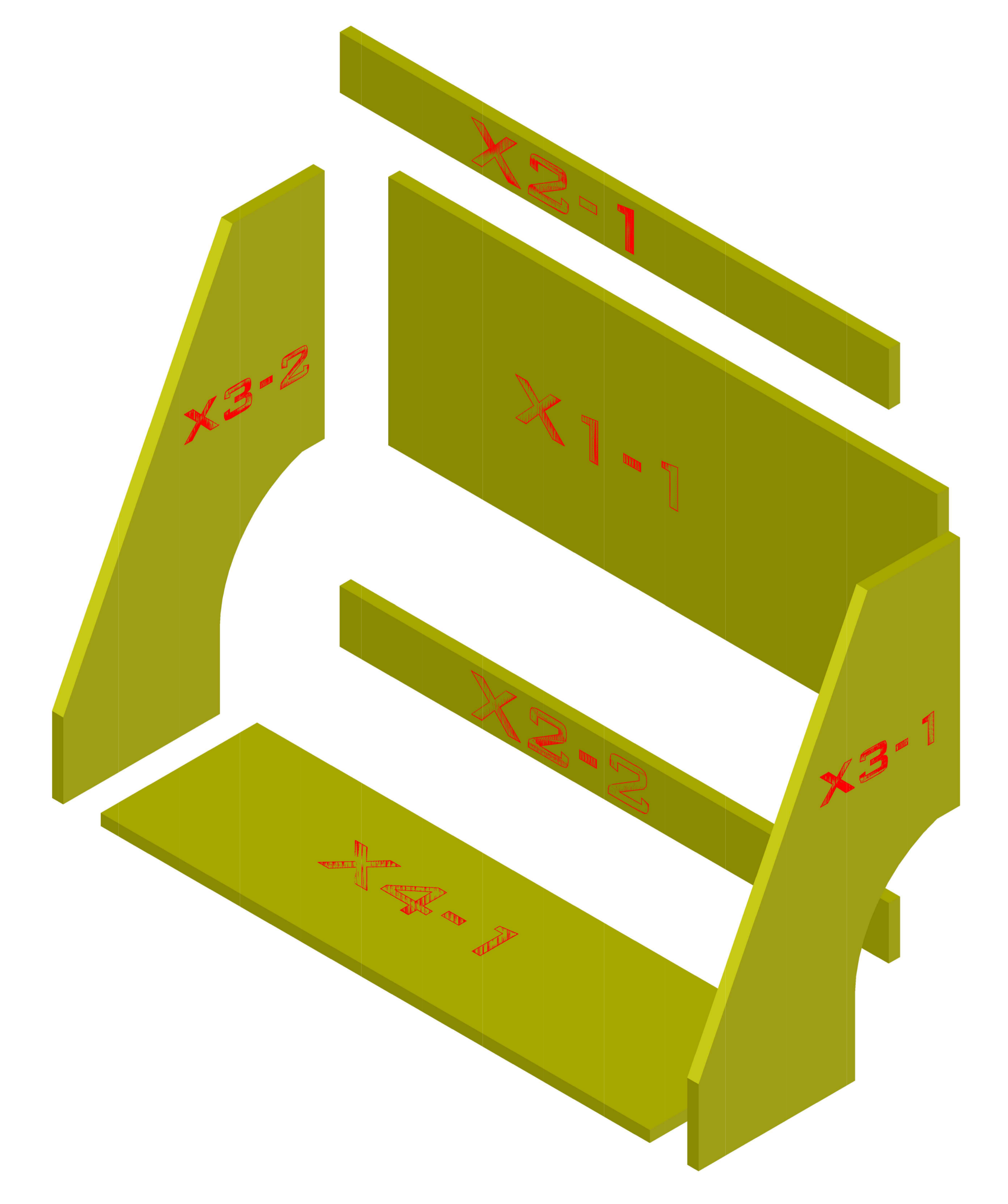
Once X has been determined, it will be sufficient to modify the pieces X2-1, X1-1, X2-2 and X4-1 of the X axis as well as all the pieces Y5 and Y3 of the axis bearing in mind that the pieces X4-1 Y5-1 and Y5-2 must be cut while maintaining symmetry.
2. Changing the length of the Z axis (TAV B)
- Same considerations made above for the X axis as regards the usefulness of the modification. To implement the change repeat the above measurement


In this way the Nema23 touches the table, no shims are required and assembly is easier. To make this modification it is sufficient to modify the piece Z1-1.
3. Changing the shoulder width (TAV C)
- This allows to increase the working width of the machine but bearing in mind that the reduction of the arm increases the stresses on the shoulder itself
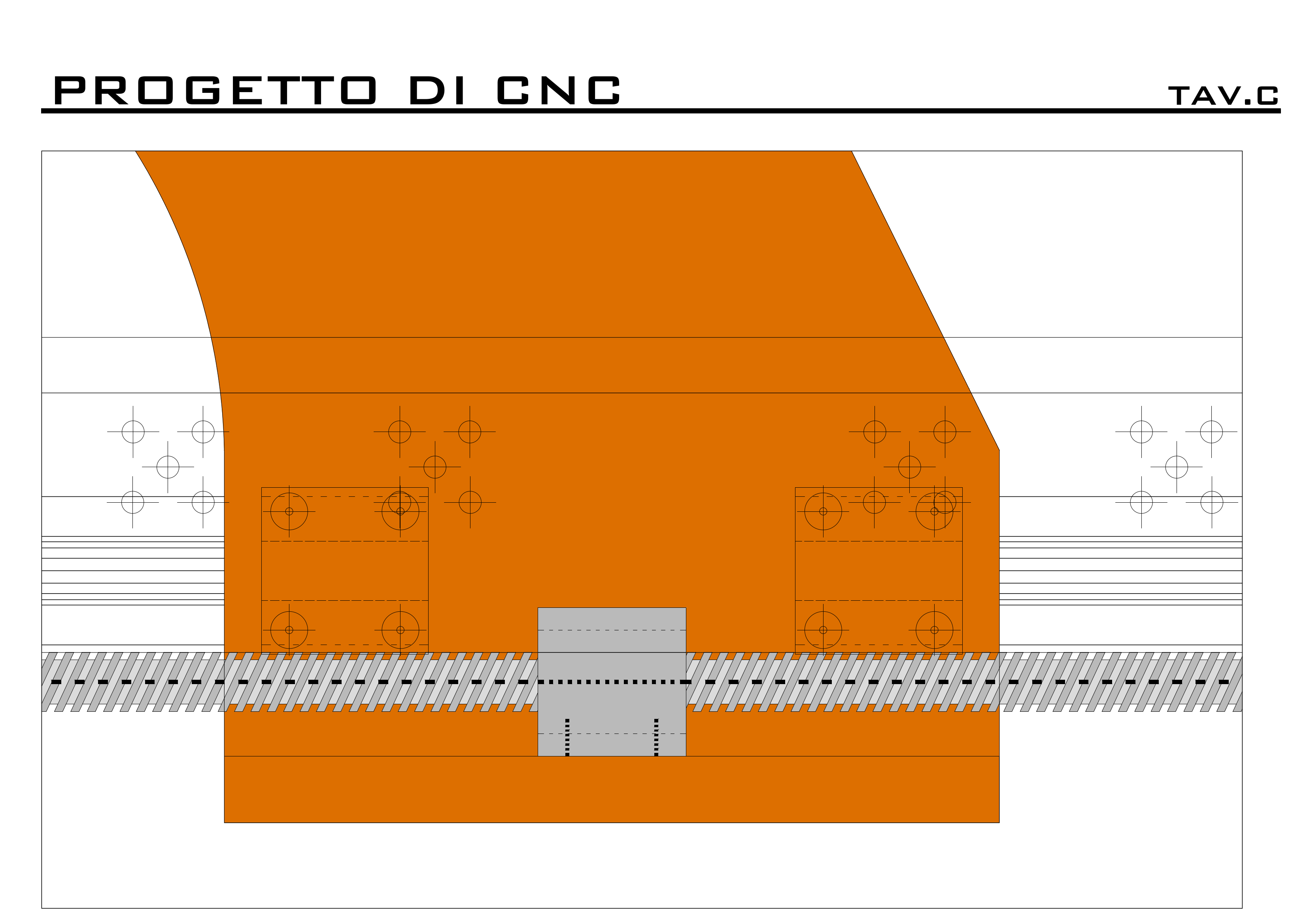
To carry out this modification it is sufficient to modify the width of the pieces X3 and modify the position of the holes of the pads on them.
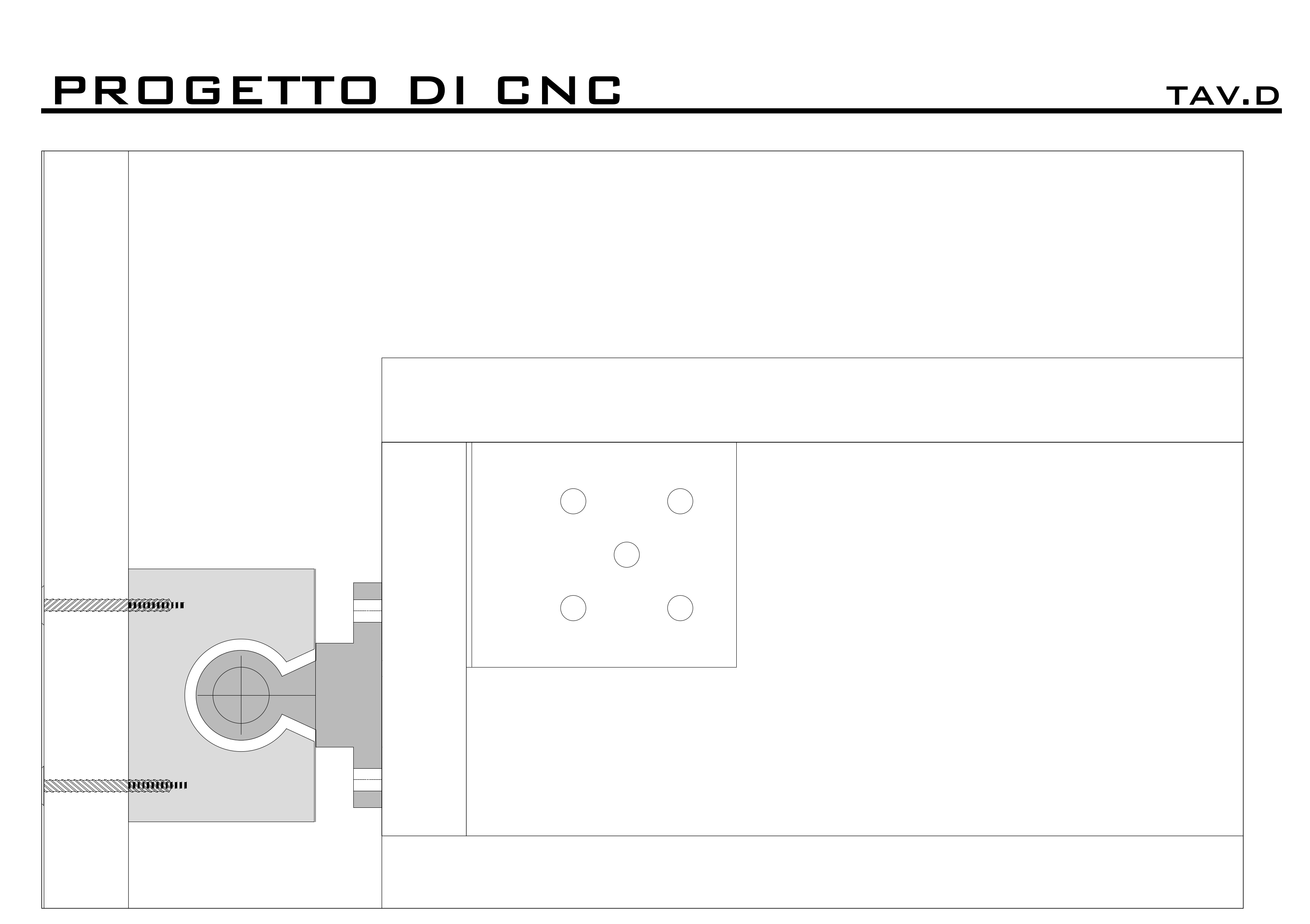
4. Brackets issue (TAV D)
- In the first analysis, keep in mind that their dimensions may vary so pay attention to the drilling
- Improvement of rigidity with provision of metal angles in the joints X4-1 and X3-1 and X3-2 as well as X1-1 and X3-1 and X3-2
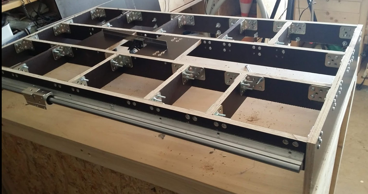
- Increased height of the tables (Y axis Y4-1 and Y4-4) so as not to overlap the holes of the SBR guides on the brackets. I preferred to keep it low so as not to increase the arm, and therefore the stresses. In fact, it should be noted that the greater the distance of the guides from the work surface, the greater the arm that is created between the tip of the spindle cutter and the horizontal axis of the guides. So I increase the forces involved.
As you can see from the photo below, the SBR guides overlap the stiffening brackets. I opted for this solution as I did not want to lower the guides too far below the work surface (As mentioned, the greater the distance of the guides from the surface, the greater the stresses that will be created on them due to the increase in the arm and therefore the twists. ). This does not mean that you cannot find a better solution, such as bringing the guides flush and moving the brackets down so that they do not overlap. Keep in mind, however, that the only problem deriving from the overlap is that in some cases you will have to drill them to pass the fixing screw of the guides. Another possible solution consists in checking the fixing holes on the guides exactly and making sure that the support brackets never overlap with the aforementioned holes by suitably moving the boards on which they are anchored.
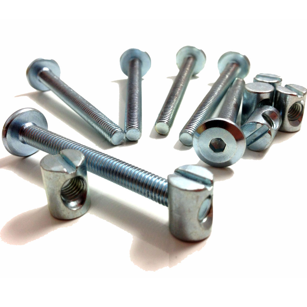
Finally, I point out that in a first hypothesis, in place of the brackets, I had considered the use of carpenter's screws such as those below. Probably by placing 3 at each joint in place of the brackets, the same stiffness result could be obtained. I preferred the brackets mainly in order not to have screws in tension on the wood which could have caused deformations over time.
6. Shoulder inclination and spindle position (TAV E)
- In relation to what will be the spindle you are going to use, given that they have different attachment diameters, it would be good to adjust the inclination of the shoulder in such a way that its axis falls exactly on the centerline of the line that joins the two shoes of the shoulder itself
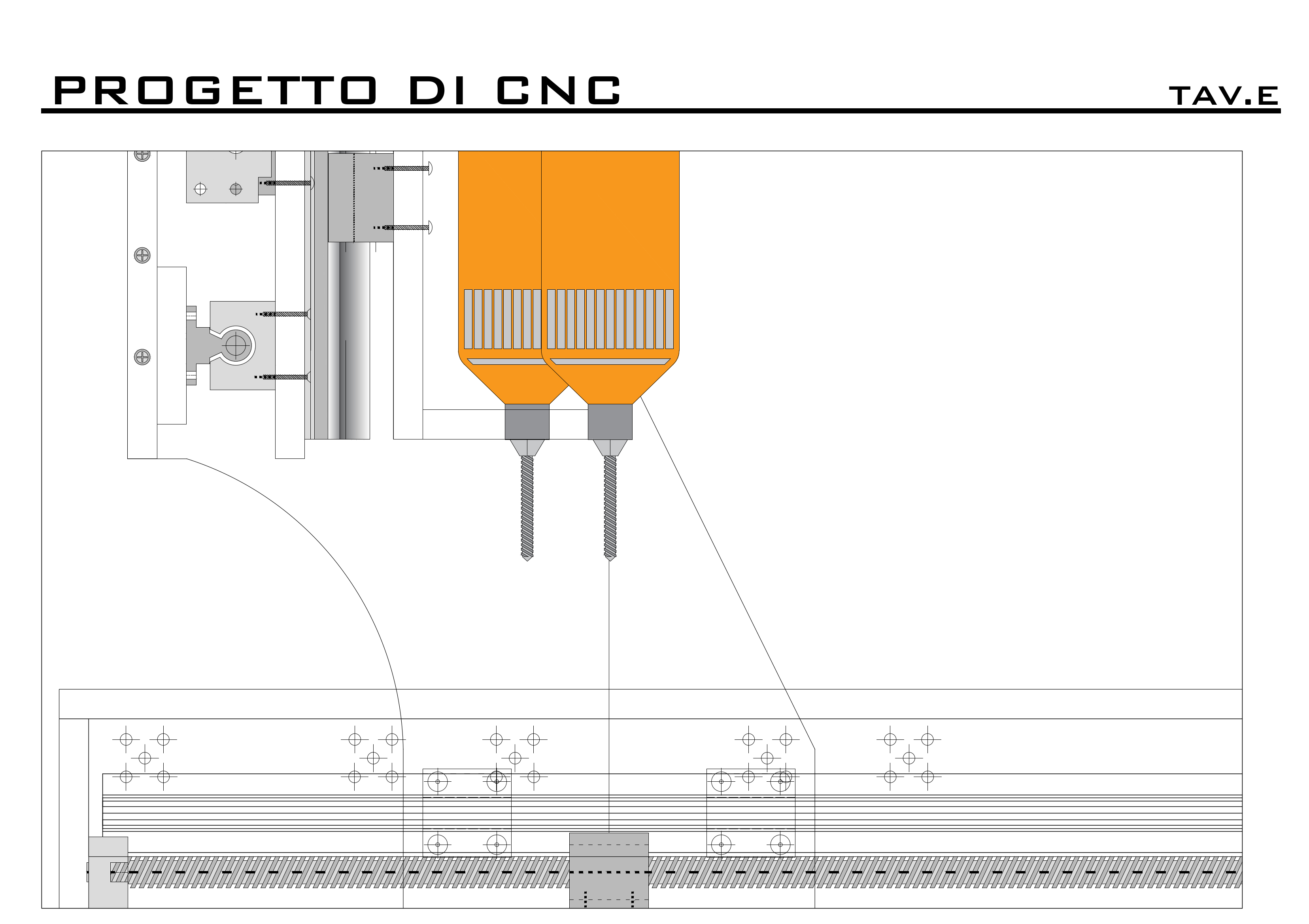
To carry out this modification it is possible to operate in two ways by intervening in both of the pieces X3.
First case: I change the inclination of the X3 boards, and then I move the rear part forward
Second case: I leave the inclination of the shoulder unchanged and move the back part forward
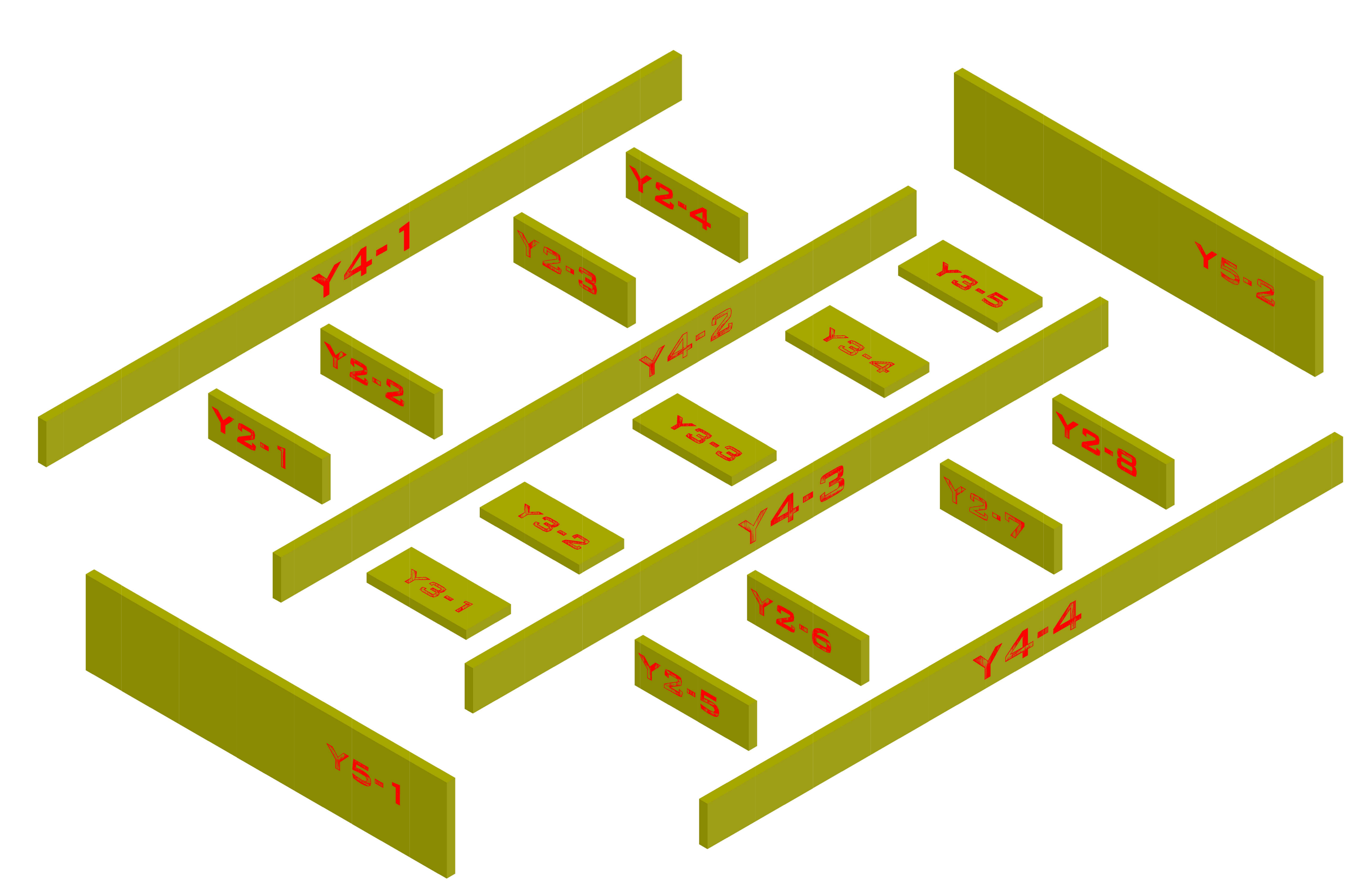
Additional considerations Y axis
As regards the fixing of the screw supports BF and BK relative to the Y axis, the following must be highlighted. Unlike the X and Z axes, the Y axis does not have the table on the bottom which allows the fixing of the above mentioned components using the vertical holes. These, in fact, must be fixed with the front holes on the boards Y5-1 and Y5-2. This means that the motor cannot be mounted following the modifications proposed for the other two axles and therefore requires spacers. If desired, it can be remedied by inserting a specific support or, as some do (but it is a solution that I do not agree with), eliminating the support of the screw on the motor side.
To adapt the axis to the screw measurements you have, simply repeat the measurement operation above and then change the lengths of Y4 from 1 to 4.
Screw-Motor connection joints
If you have purchased a kit including SBR guides and screws, you will most likely have also delivered the connection joints. These, in almost all kits, will match the ones in this photo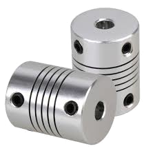
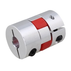
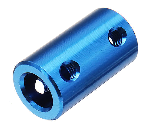
If yours match those in the picture, further advice is to replace them (at least for the x and y axis) with others. I recommend using one of these templates
 |
 |
Finally, I remind you that on the channel there is::
- a complete playlist of all construction stages to the following LINK
- a playlist with the processing tests to the following LINK
- a playlist with the processes carried out with the machine to the following LINK